Add to Cart
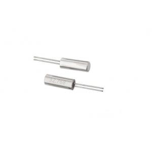
Electronic components 32.768KHZ 12.5PF 10PPM QUARTZ CRYSTAL UNITS X206032768KGB2SC Directly inserted cylindrical crystal oscillator
Part number:
| Package type | Part number | Model Number |
| 2P 2060 | X206032768KGB2SC | YT-26 |
| 2P 3080 | X308032768KGB2SC | YT-38 |
Description:
| Frequency (HZ) | 32.768KHZ |
| Frequency offset (PPM) | ±10PPM |
| Voltage (V)/ Load (PF) | 12.5PF |
| Working Temperature | ,-20℃~+70℃ |
| Dismensions (mm) | 2.0mmx6.0mm |
Reliability Test Items
1. Mechanical Performance Tests
| Shock |
Orient the sample in any attitude and drop it three times from a height of 75 cm onto a hardwood board with a thickness of 3 cm
|
| Vibration | Subject the sample to 1.5-minute cycles of frequencies of 10 to 55 Hz and amplitudes of 1.5mm for two hours in each of the X,Y, and Z directions, or 6 hours in total. |
| Tensile strength of terminal | Apply a 1.5Kg tensile load to each terminal and sustain it for 30±5 seconds. |
| Bending strength of terminal |
Apply a 0.5 Kg load to one of the terminals, and after tilting the main unit for 90°,restore to its original attitude. Then, tilt it in an opposite direction for 90°,and restore to its original attitude |
| Solder ability | Dip terminals in RMA flux for5 ± 0.5 seconds. Under room temperature. Dip terminals in a 230±5℃ solder bath for 5±0.5 seconds. The solder shall leave an undipped terminal length of 2 mm at their base . |
| Resistance to Soldering Heat |
Dip terminals in a 260±5℃ solder bath for 10±0.5 seconds. The solder shall leave an undipped terminal length of 2 mm at their base |
| Leaking Test | Take measurements with a helium leakage detector,or measure insulation resistance under pressure. |
Specifications:
| Specification Number | Specifications |
| A | Any variation between the pre- and post-test frequencies shall remain within ±5ppm. The post-test equivalent series resistance shall remain within its specified tolerance range. |
| B | Any variation between the pre- and post-test frequencies shall remain within ±10ppm. The post-test equivalent series resistance shall remain within its specified tolerance range |
| C | After each test, no visible damage shall be manifested, nor shall the hermetic seal break down. |
| D | At least 90% of each dipped area shall be covered by fresh solder |
| E | 1×10⁻² μPa.m3 /s Max or IR≥500MΩ |
Remark:Measurements shall be taken at 25±2℃,and after each test, the sample be exposed
to two hours at 25±2℃


